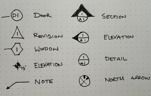
There are slews of symbols on the construction document sets that to the untrained eye are terrifying. I’ll break it down into a few sub-categories.

First there are the Tags. These are non-geometry information that explain what a geometry is or to find more information on that geometry.
- Door Tag – Every door is accompanied with its tag, often on an enlarged floor plan
- Revision – Every time that a drawing is revised and you need to communicate to stakeholders that only a small part of the set has been revised, these triangles and their accompanied revision clouds will appear
- Window – Every door is accompanied with its tag, why not windows? Well, curtain walls and windows are kinda tagged differently. For the most part, hexagons normally represent a thing you can look through
- Elevation – Yin/Yang looking thing that makes a crosshair, I suppose, showing the accuracy of the elevation you are marking
- Note – Going to need its own blogpost, honestly. For the most part this arrow is accompanied with helptext for stakeholders to understand what a thing the architect has drawn actually is
- Section – Pretend you cut a building open like a cake. The profiles of the edges of the building explain how structure and systems work together. This tag shows, normally, where that cut line is, and the page its section cut reference is on
- Elevation – Same as section, but the tag is referencing only a view. Elevations are useful for crafting space: locate light switches, material allocation, and vertical placement of windows/ doors
- Detail – Tag a thing with this to say there is more where this came from on another page, likely with higher scale and detail
- North Arrow – Alerts user to where up is, and why it is or is not geographic north

- Line – The shortest distance between two points is this
- Centerline – Dash with single dot – Often used to mark the center of an object
- Boundary – Dash with double dot – Often used to show where property begins and ends
- Dotted – All dots – Often used to show things above (in plan) or things that will be demolished, or things that currently exist.
Scales
As the users drawing becomes smaller at a higher scale, the symbols need to stay the same size on a piece of paper–words need to stay consistently at 3/32″ tall regardless of scale. This annotation system is super annoying when needing to handle slews of graphic scales, all with different scaling factors, and reasons their underlying drawings are the scale that they are
Variety list of scales from a CD set I just reviewed:
1″ = 160′ Overall Site Plan (Scale your 3/32″ text by x1920)
1″ = 60′ Arch Site Plan (Scale your 3/32″ text by x720)
1″ = 40′ Overall Floor Plan (Scale your 3/32″ text by x480)
1/32″ = 1′ Partial Roof Plan (Scale your 3/32″ text by x384)
Stuff still to unpack on symbols: every set uses different symbols. Will need a flexible symbol system.
